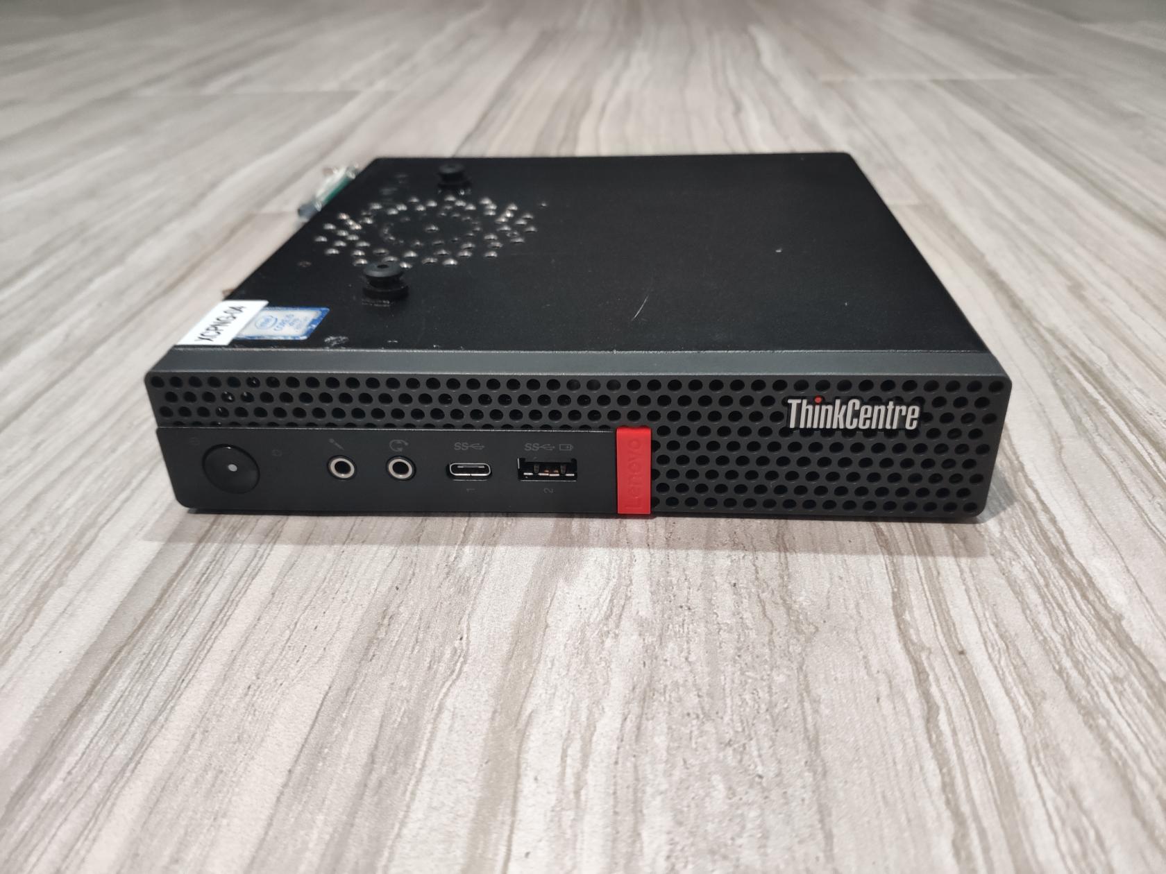
Lenovo M720Q/M920Q Tiny Dual M.2 Mod
The Lenovo M720Q and M920Q are from the Lenovo Tiny 5 generation of Lenovo Tiny PCs, that supports 8th/9th Gen Intel CPUs, and up to 64GB (2x32GB) DDR4 SODIMM RAM.
8th/9th Gen Intel CPU is one of the better generation of CPU where it is now old enough to be cheap on the secondary market, and is new enough that it can handle many homelab services without breaking any sweat.
The iGPU inside 8th/9th Gen Intel CPU supports being passthrough to VMs via the Intel GVT-g technology, allowing services such as Plex and Handbrake to take advantage of Intel Quick Sync media encoder/decoder engine.
The M720Q and M920Q is a rare model among the Tiny series as it supports half-height, half-width PCIe cards, via a special riser. For homelab, this means that you can have a tiny PC form factor compute host with 10G networking capability.
You can learn more about this generation of Lenovo Tiny (as well as other Tiny generation) from the amazing community at ServeTheHome forum, https://forums.servethehome.com/index.php?threads/lenovo-thinkcentre-thinkstation-tiny-project-tinyminimicro-reference-thread.34925/
Dual M.2 NVMe Mod
The M720Q and M920Q are the lower tier version of another Tiny model, the M920X, with some components missiung. Most notably, the M920X supports 2x M.2 slots instead of 1x M.2 slot like the M720Q and the M920Q.
Thanks to the open-soruce community, and the github user badger707, we can convert an M720Q or M920Q into an M920X with 2x M.2 slots, by soldering back on some components to the motherboard.
You can find the dual m.2 mod details over on Github, at https://github.com/badger707/m920q-dual-NVME?tab=readme-ov-file
Tools and Component Needed
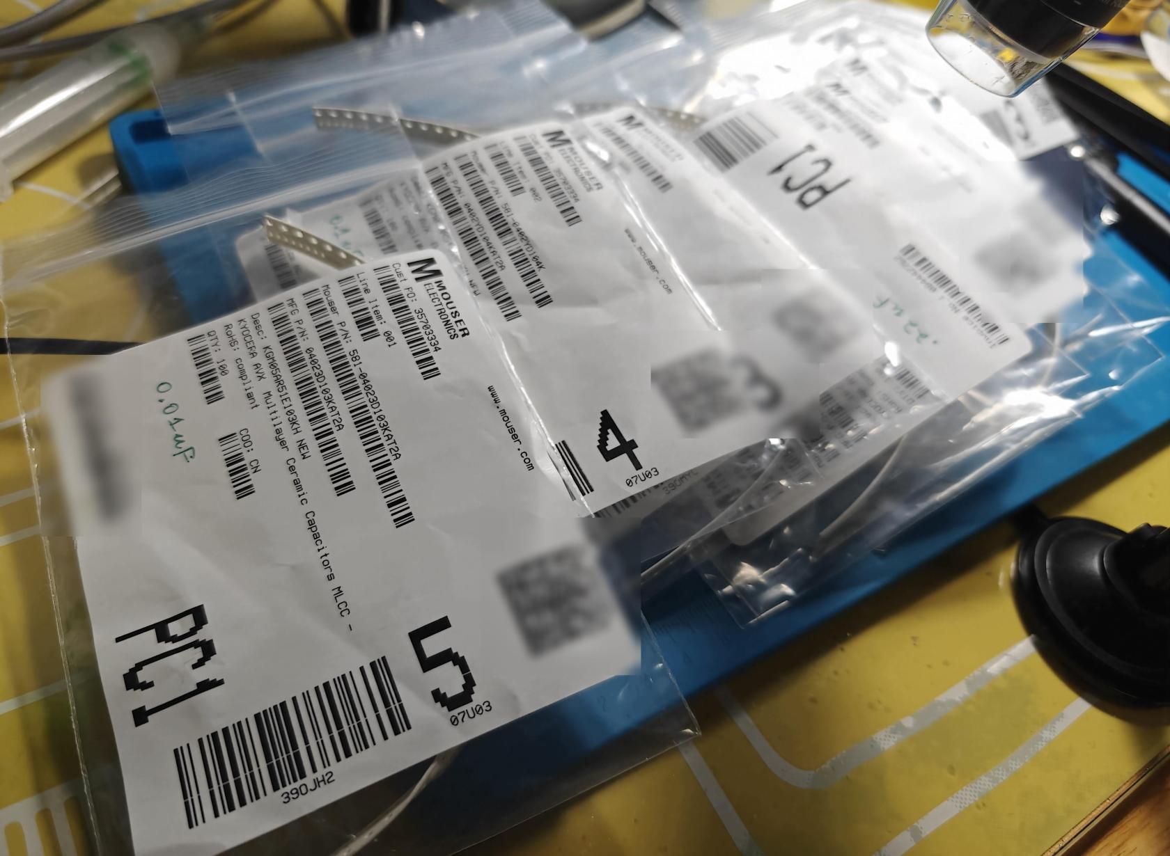
The components needed are tiny. I followed the originial github guide and ordered the necessary parts from Mouser https://www.mouser.com
If you have not done micro soldering before, plan on ordering a bunch of extra components just in case. I personally ordered 100x of each of the capacitor and resistors since they are cheap, and 10x of the NVMe connector.
| Type | Size | Value | Voltage | Count | Mouser Part Number | Link |
|---|---|---|---|---|---|---|
| Capacitor | 0402 | 0.01uF | 25V7-K | 4 | 581-04023D103KAT2A | https://www.mouser.com/ProductDetail/581-04023D103KAT2A |
| Capacitor | 0402 | 0.1uF | 16V7-K | 2 | 581-0402YD104K | https://www.mouser.com/ProductDetail/581-0402YD104K |
| Capacitor | 0402 | 0.22uF | 25V7-K | 8 | 581-KGM05AR71C224KH | https://www.mouser.com/ProductDetail/581-KGM05AR71C224KH |
| Capacitor | 0603 | 10uF | 6.3V6-M | 2 | 810-C1608X5R0J106K | https://www.mouser.com/ProductDetail/810-C1608X5R0J106K |
| Resistor | 0402 | 0 ohm | - | 8 | 603-RC0402FR-070RL | https://www.mouser.com/ProductDetail/603-RC0402FR-070RL |
| Resistor | 0402 | 10 Kohm | - | 2 |
71-RCC040210K0FKED
|
https://www.mouser.com/ProductDetail/71-RCC040210K0FKED |
| Resistor | 0402 | 33 ohm | - | 1 | 71-CRCW040233R0FKEDC | https://www.mouser.com/ProductDetail/71-CRCW040233R0FKEDC |
| M.2 NVME connector | 3.2mm | - | - | 1 | 523-MDT320M03001 | https://www.mouser.com/ProductDetail/523-MDT320M03001 |
| M.2 NVME plastic retention clip | - | - | - | 1 | N/A | N/A |
For the M.2 plastic retention clips, I didn't bother sourcing it, as my Tiny has 2 clips on the original slot already, so I can move one of them over. You can also use a regular M.2 screw post type retention bracket instead.
You will need fine soldering iron tips. I used an TS80 soldering iron with a J style tip for this.
Have plenty of flux and leaded solder too. Leaded solder melts at a lower temperature, making the micro soldering a bit easier to do. Have solder wick around too as they can help in removing excess solder.
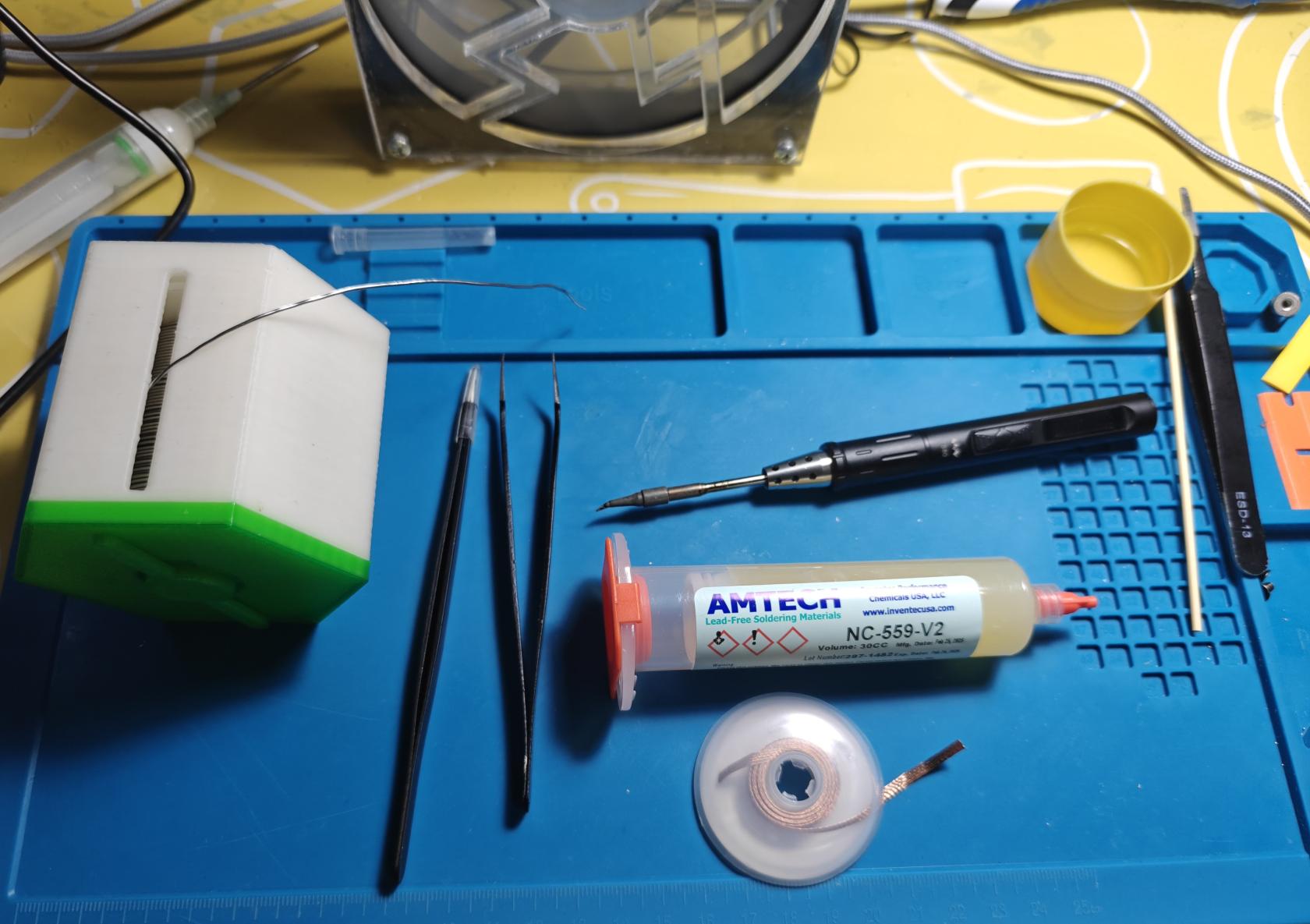
Because the components are tiny, you will need to have a good microscope to view the board, I used a USB digital microscope for this project.

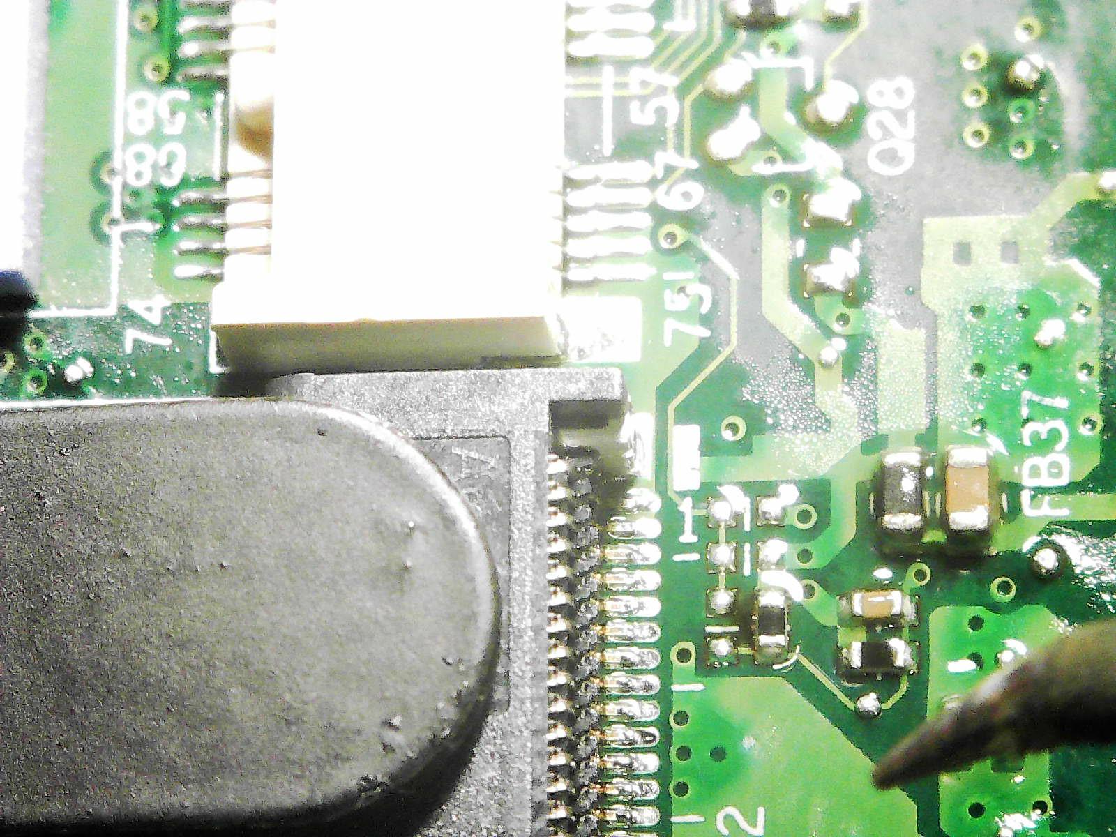
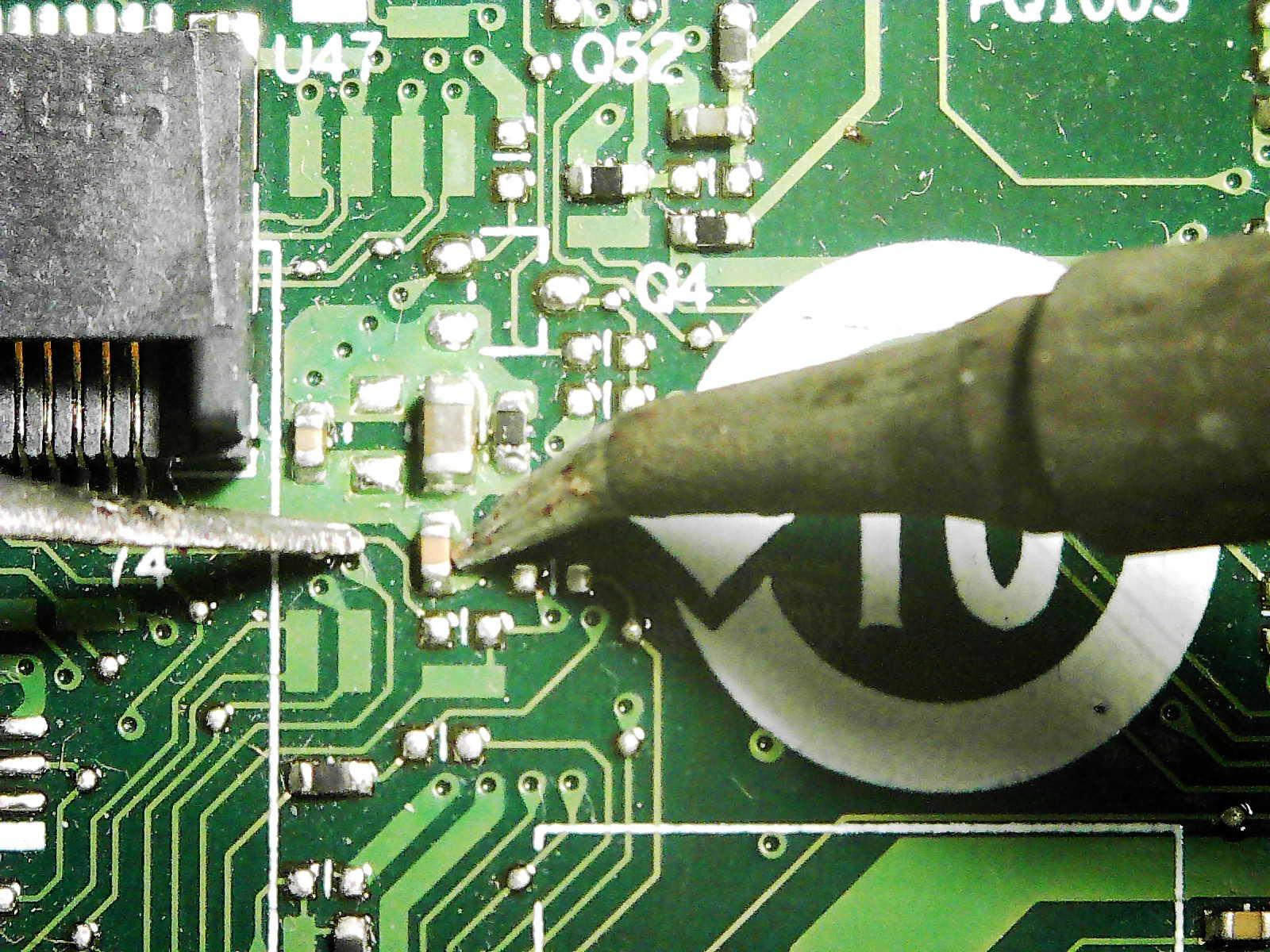
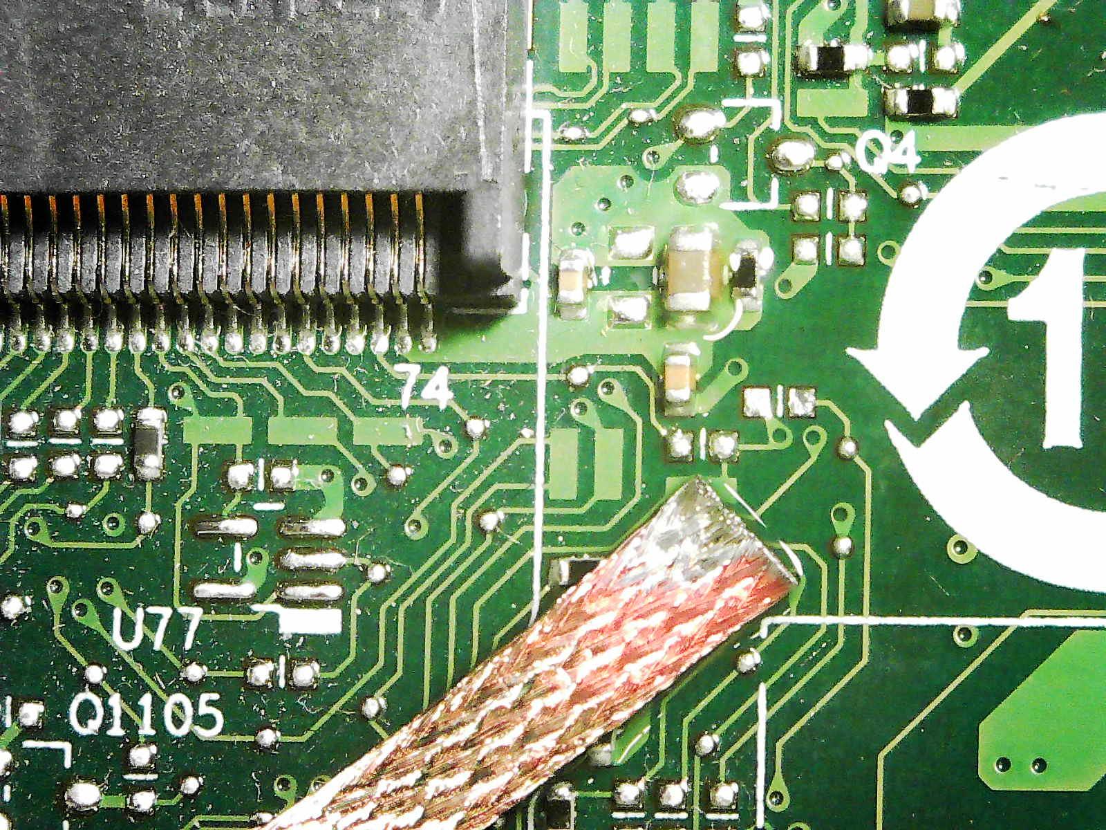
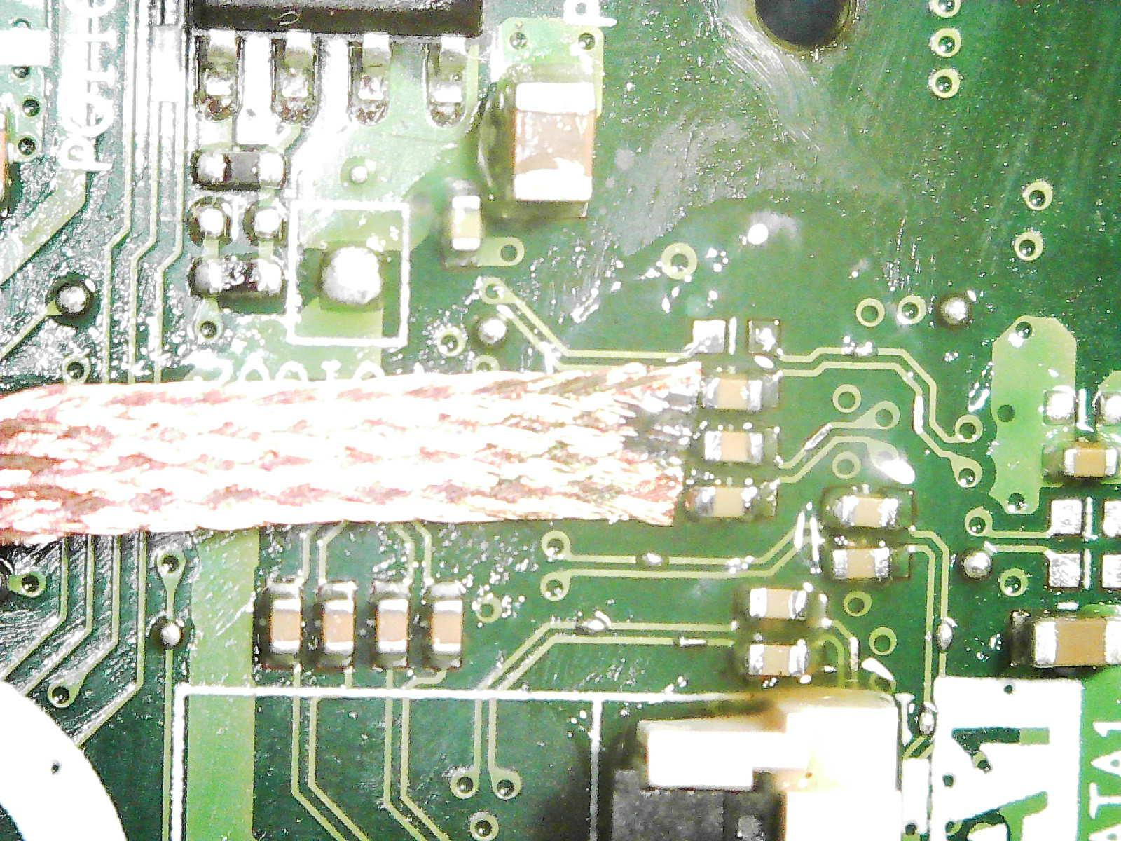
Here's a comparison picture of the soldering iron tip and tweezer tip, compared to the components on the board.
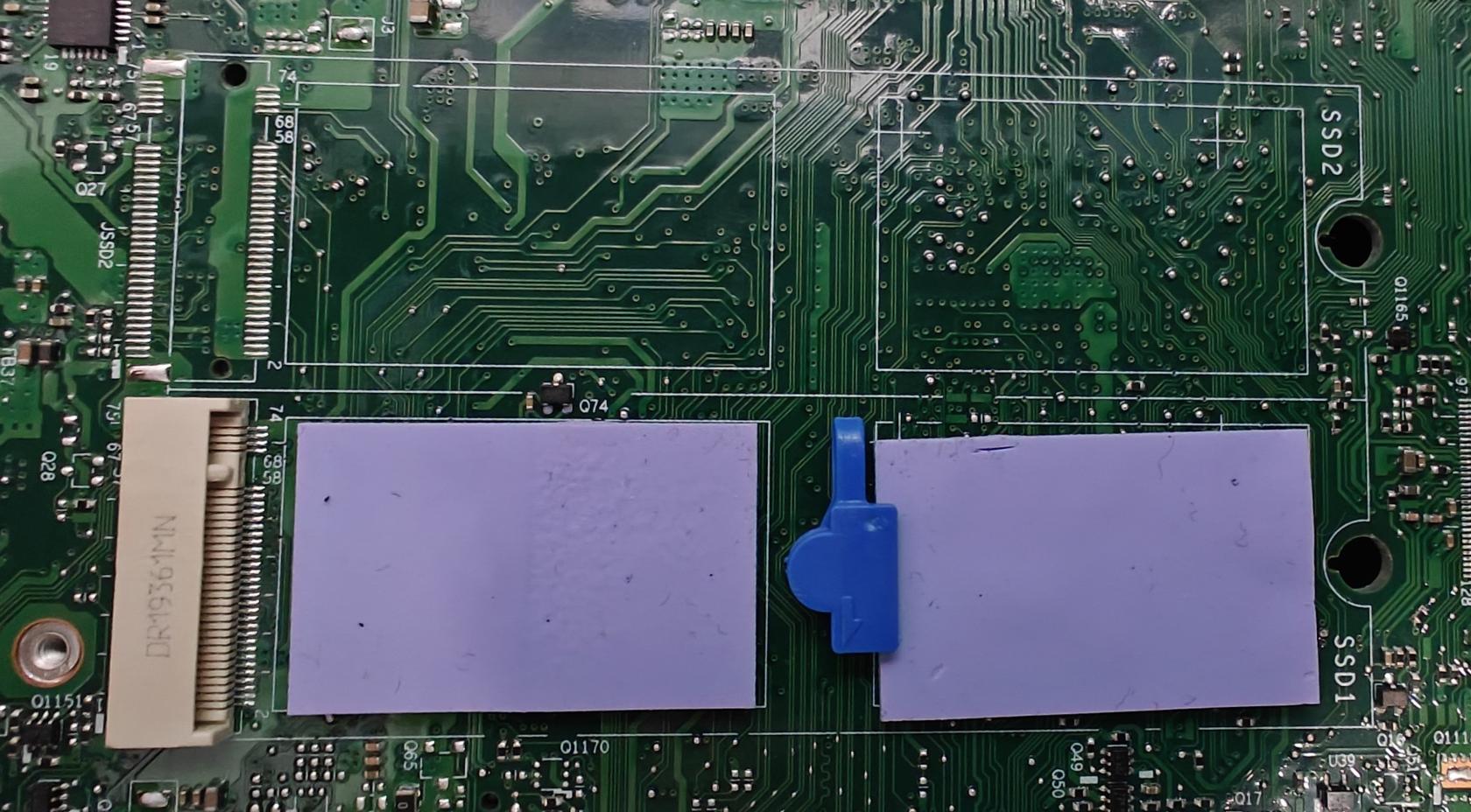
M920Q Motherboard Overview
In this guide, I am attempting the dual m.2 mod on my M920Q motherboard. The process for M720Q will be similar, with only one difference, which I will mention later on.
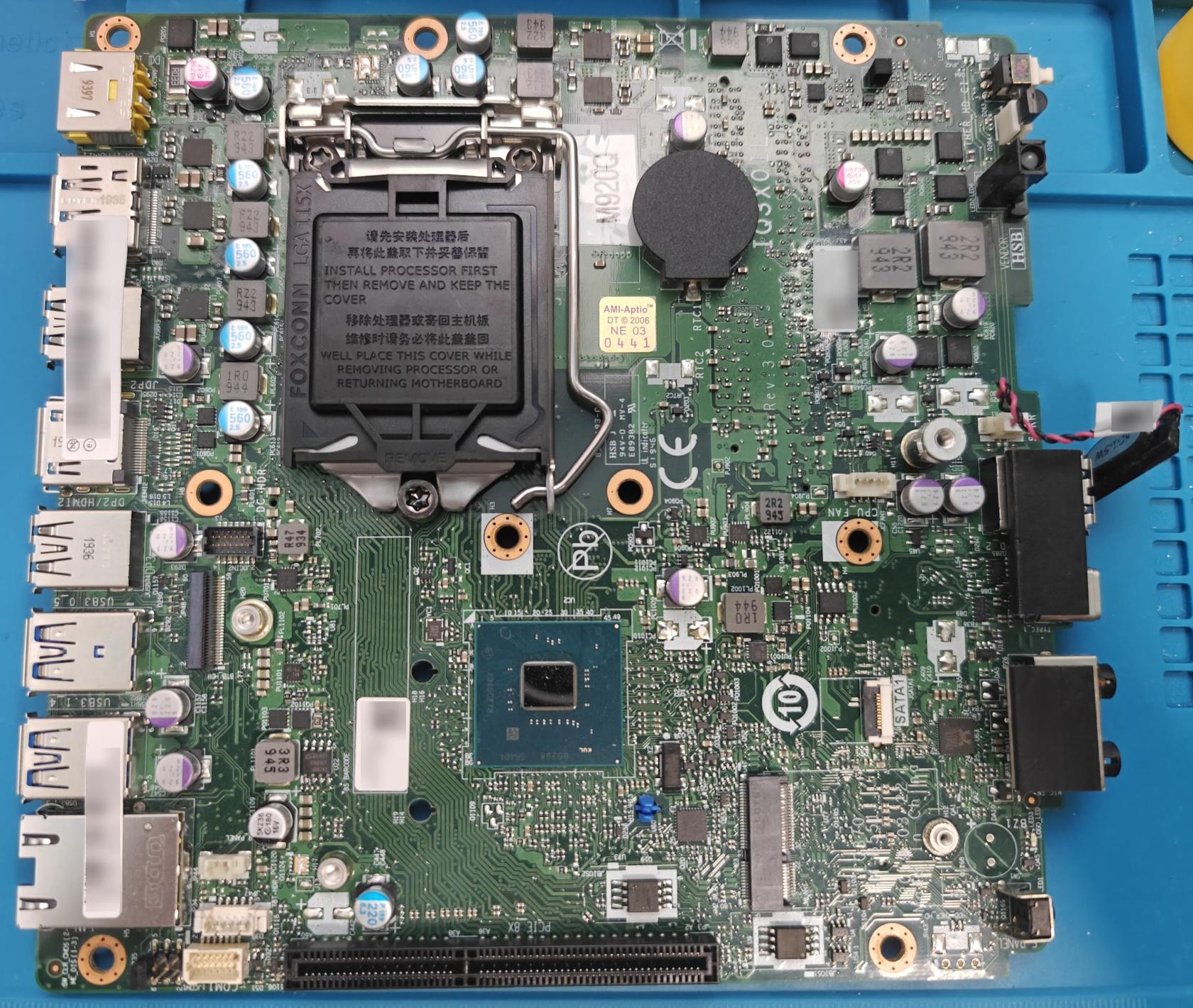
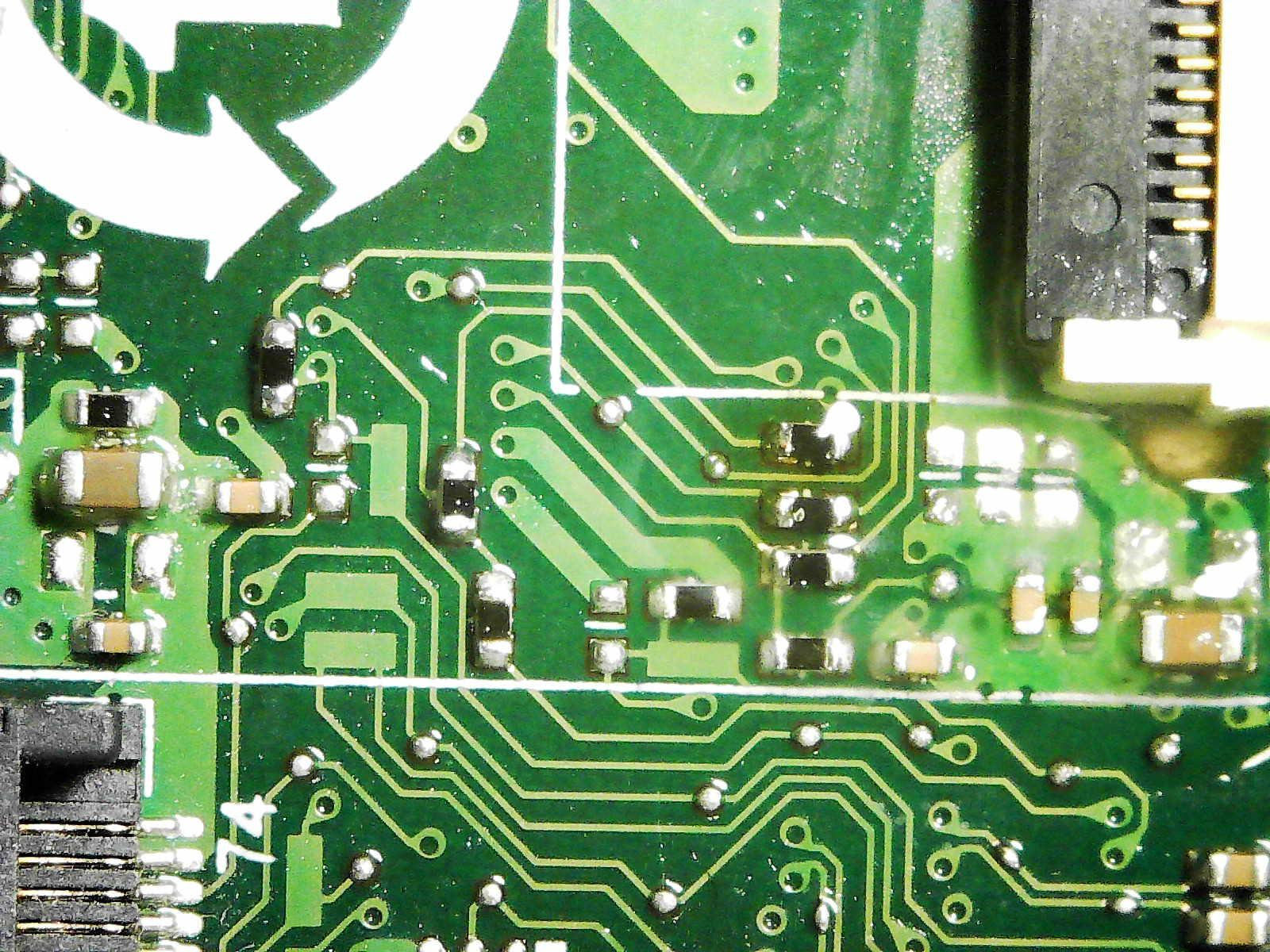
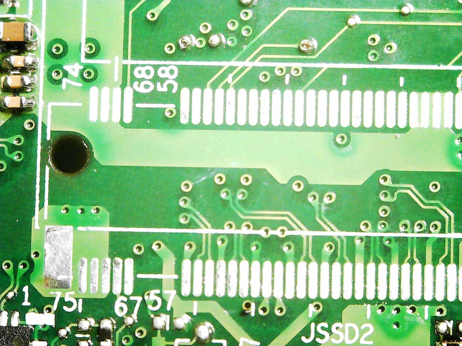
As you can see, the second M.2 slot is missing from the M720Q/M920Q motherboard.
Soldering the Components
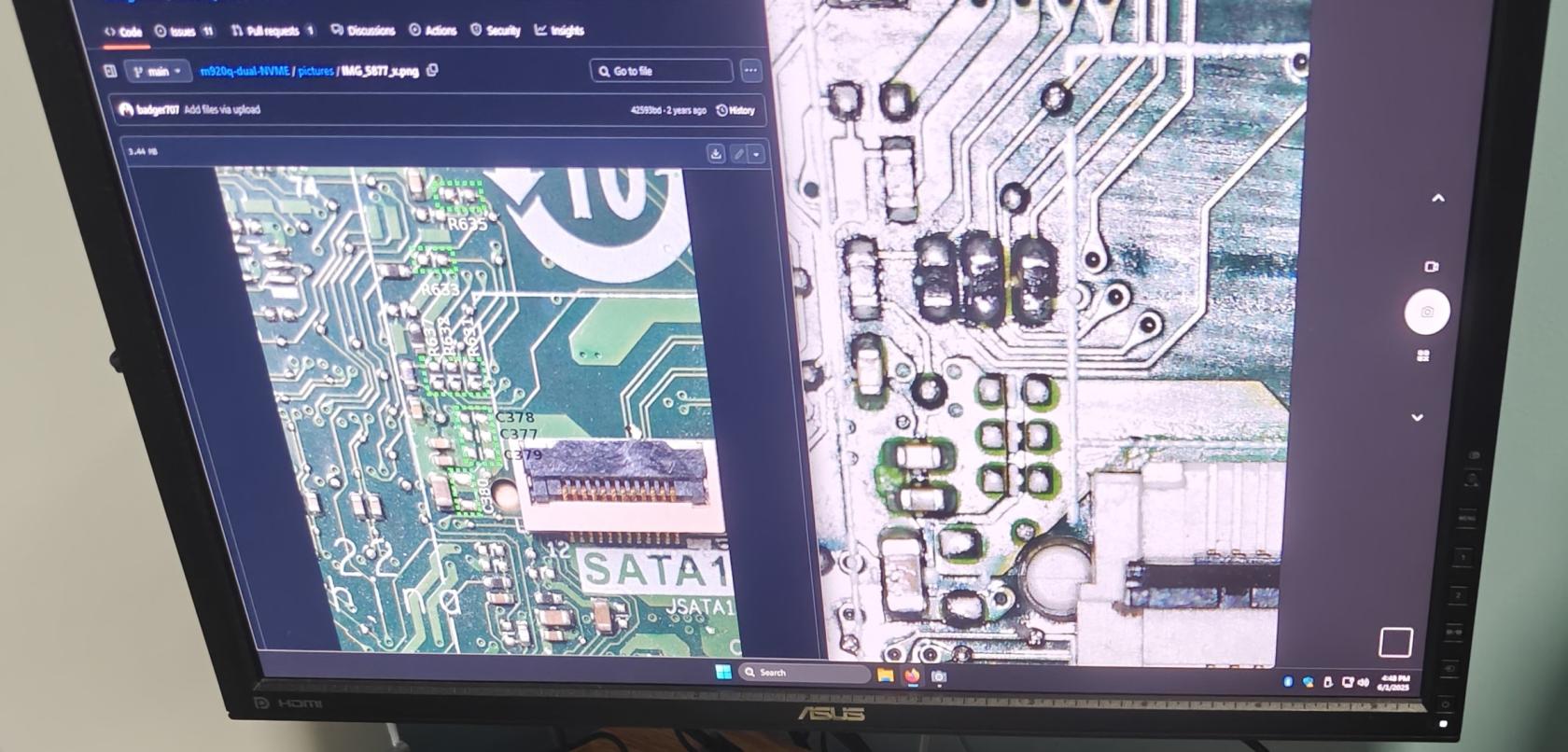
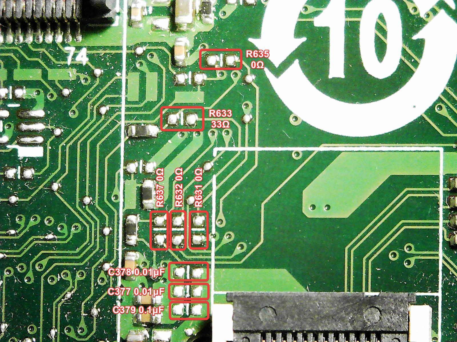
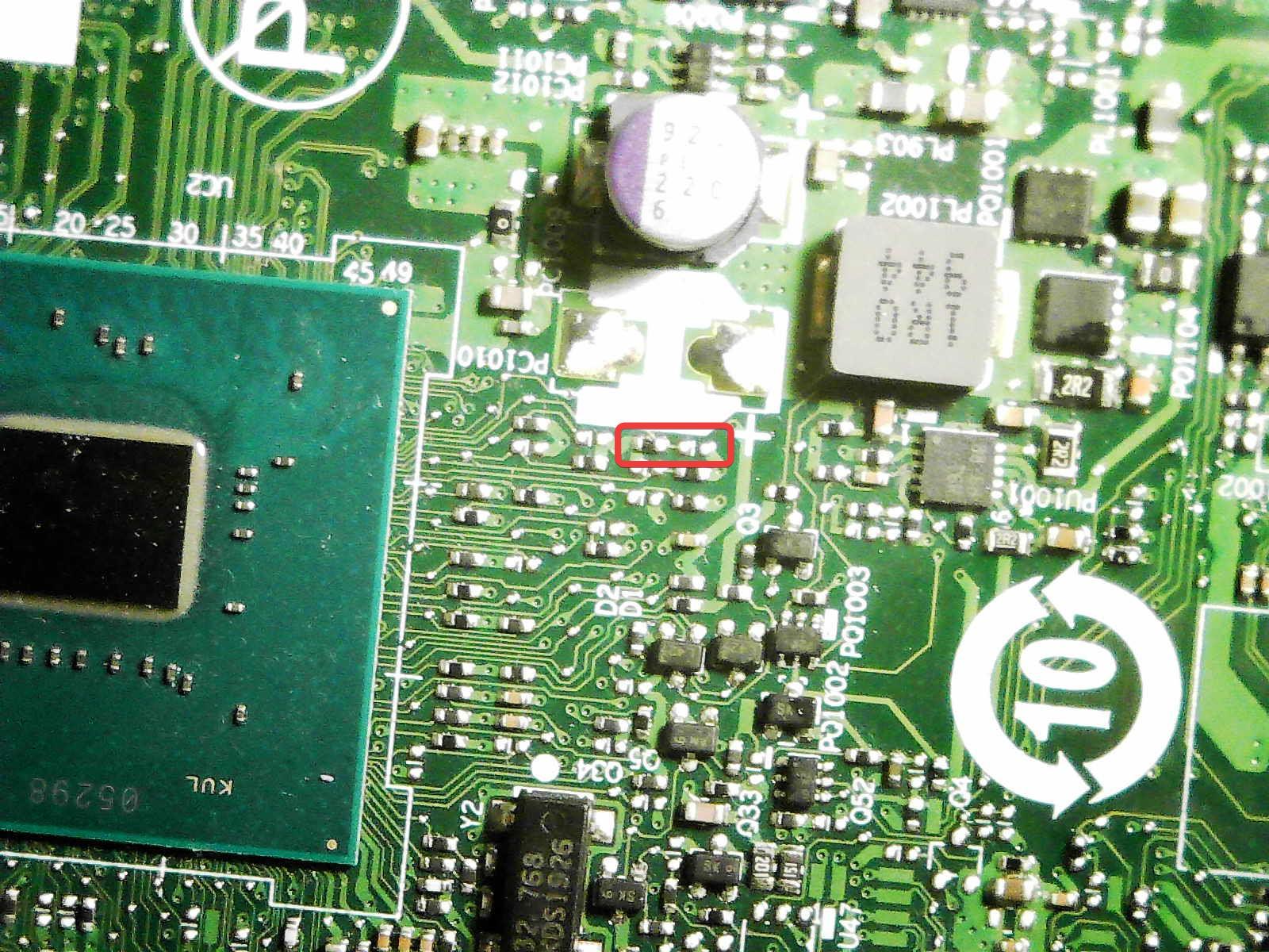
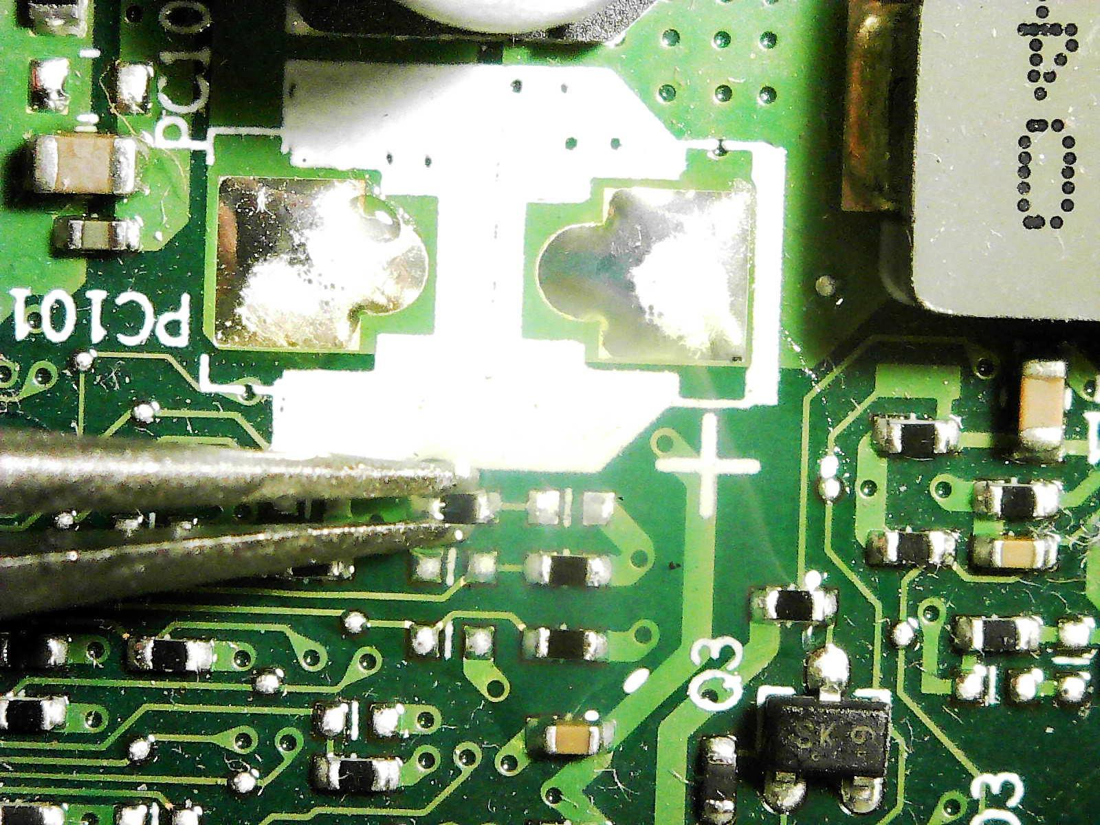
We will start around the SATA port area, near the large 10 label on the top side of the motherboard.
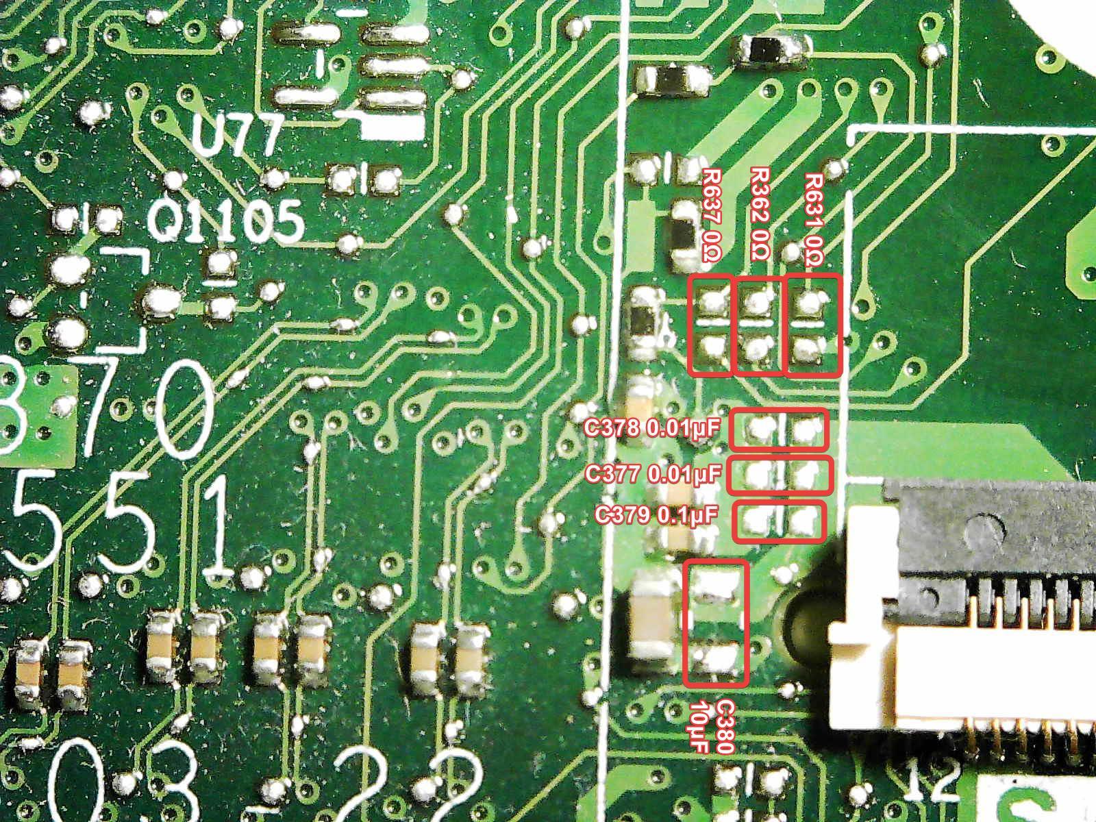
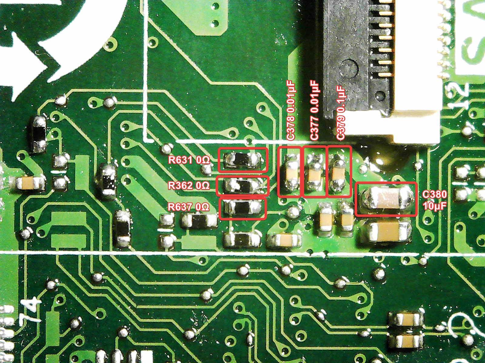
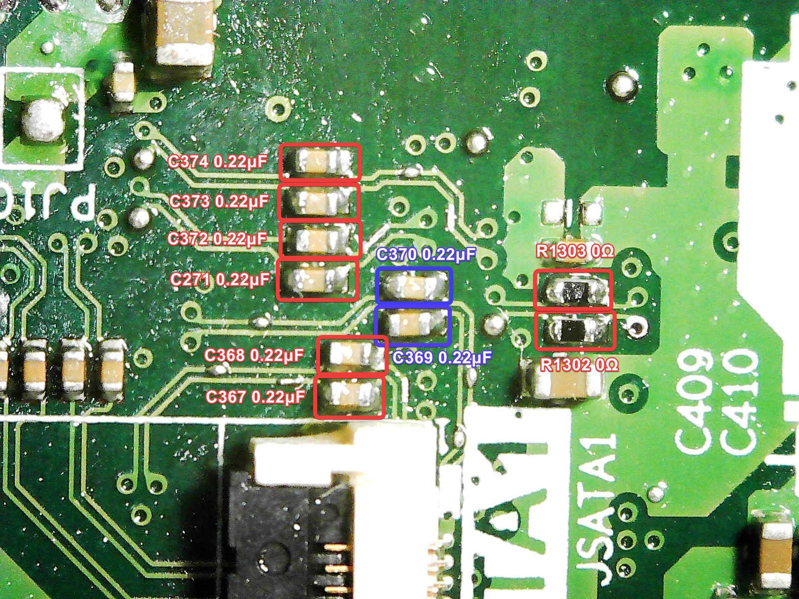
Below are the components location that needs to be solder on.
Apply plenty of flux to the component area.
Use solder wick to suck up the factory solder from the board if needed. Factor solder often are non-leaded solder, which means it melts at a much higher temperature. This can get in the way of having a nice solder joint for the component.
Take your time, and go slowly with the soldering. Apply more flux as needed.
The area near the SATA ports can be a bit tricky to do, as it is very close to the plastic.
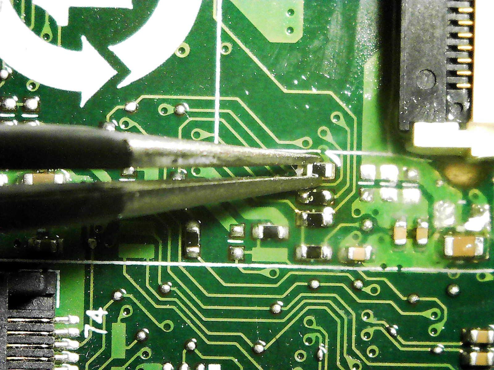
Rotate the board area to help with the tweezer placing component on the board.
Left side of the SATA port is all done!
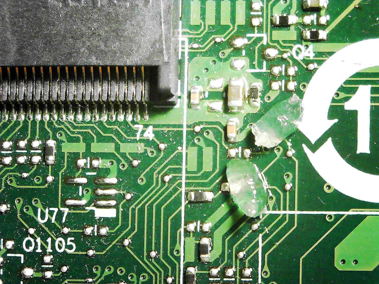
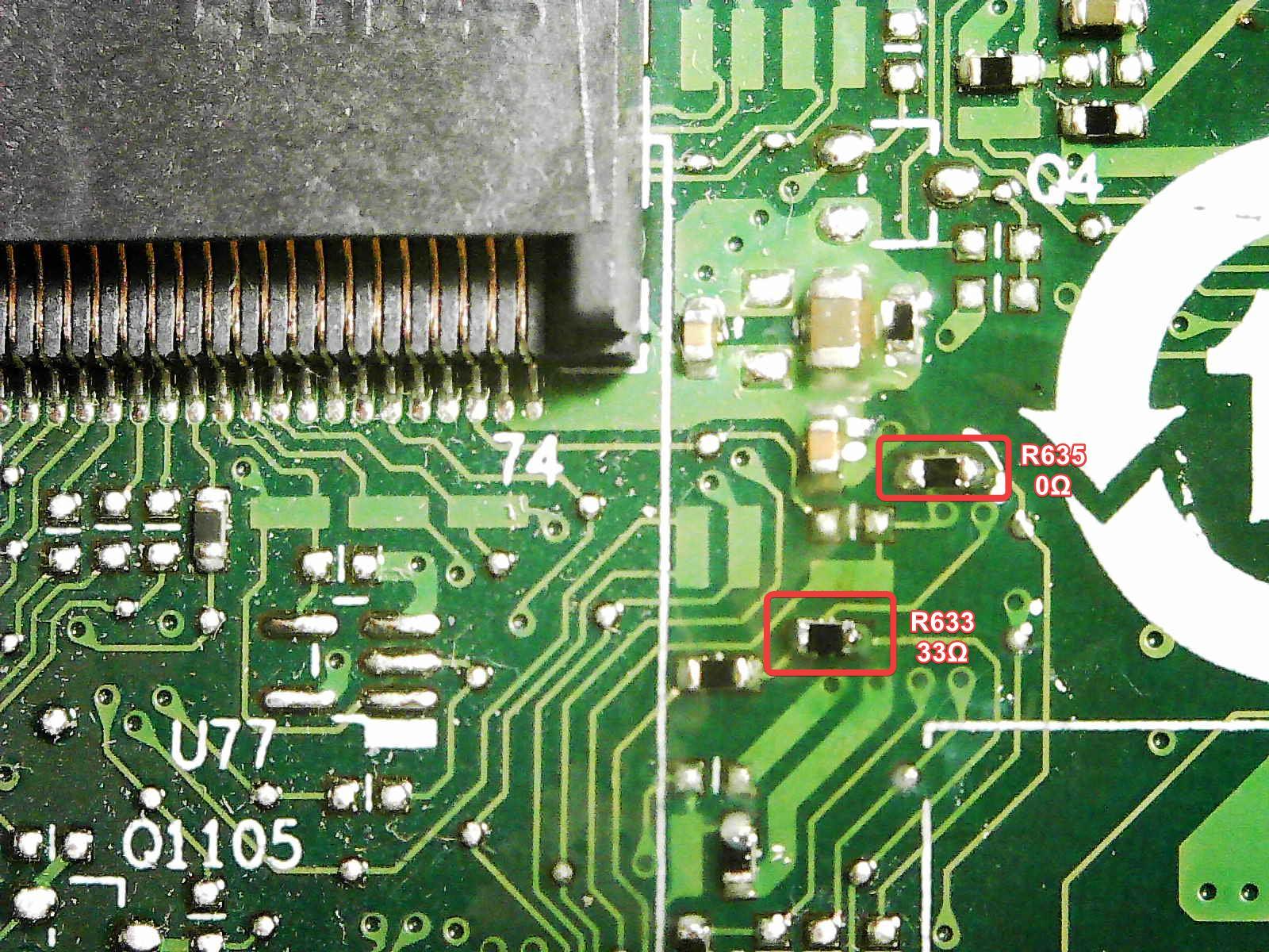
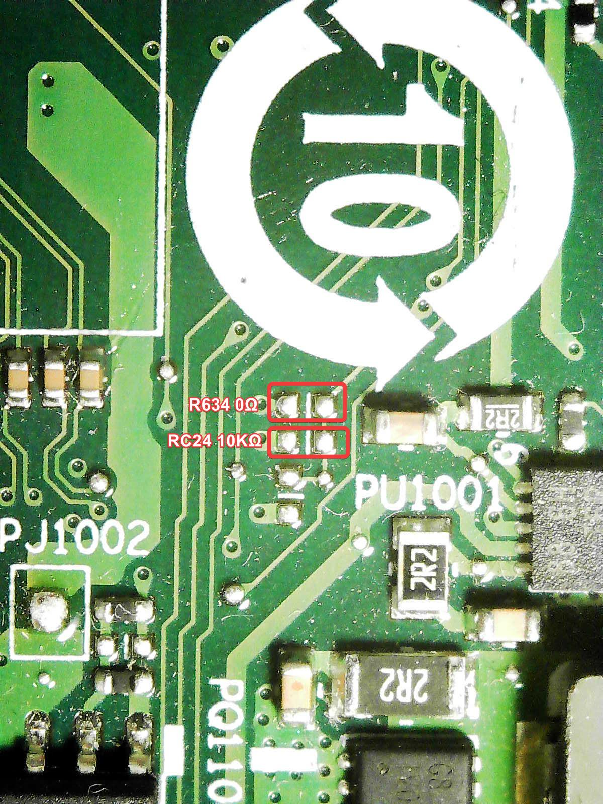
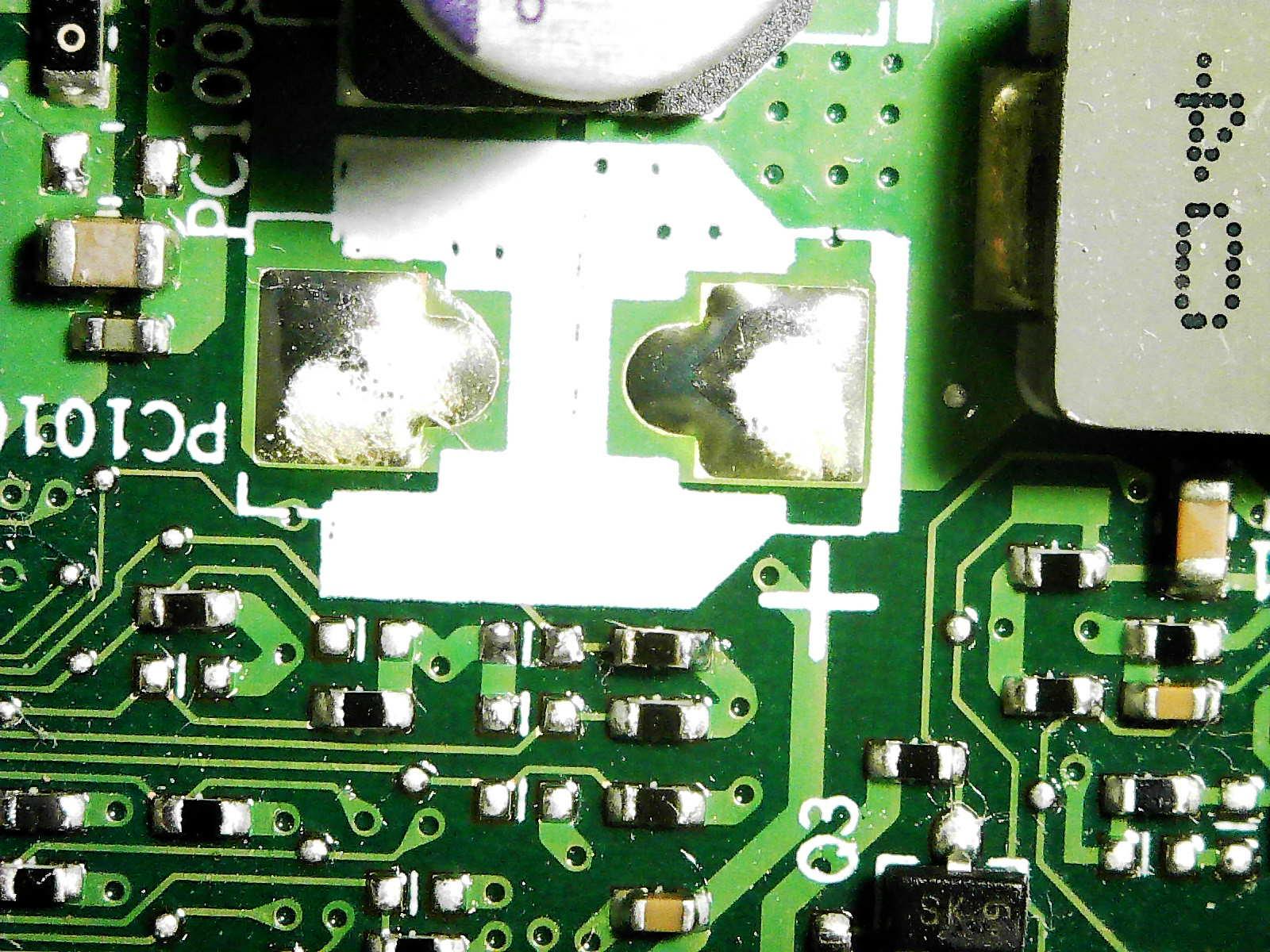
Moving onto the right side of the 10 label, there are two components to be sodler on.
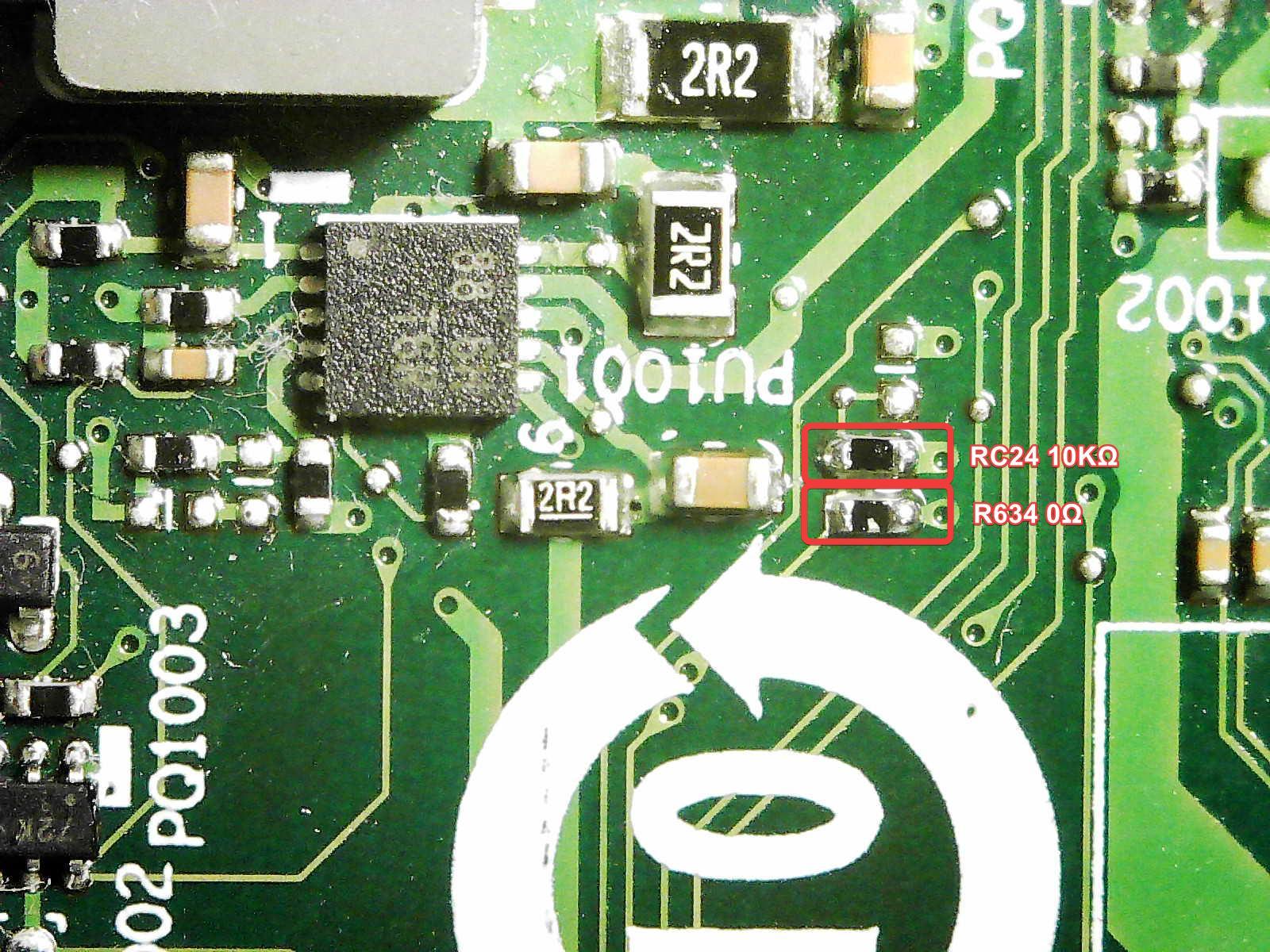
On the right side of the SATA port, there are a few more components.

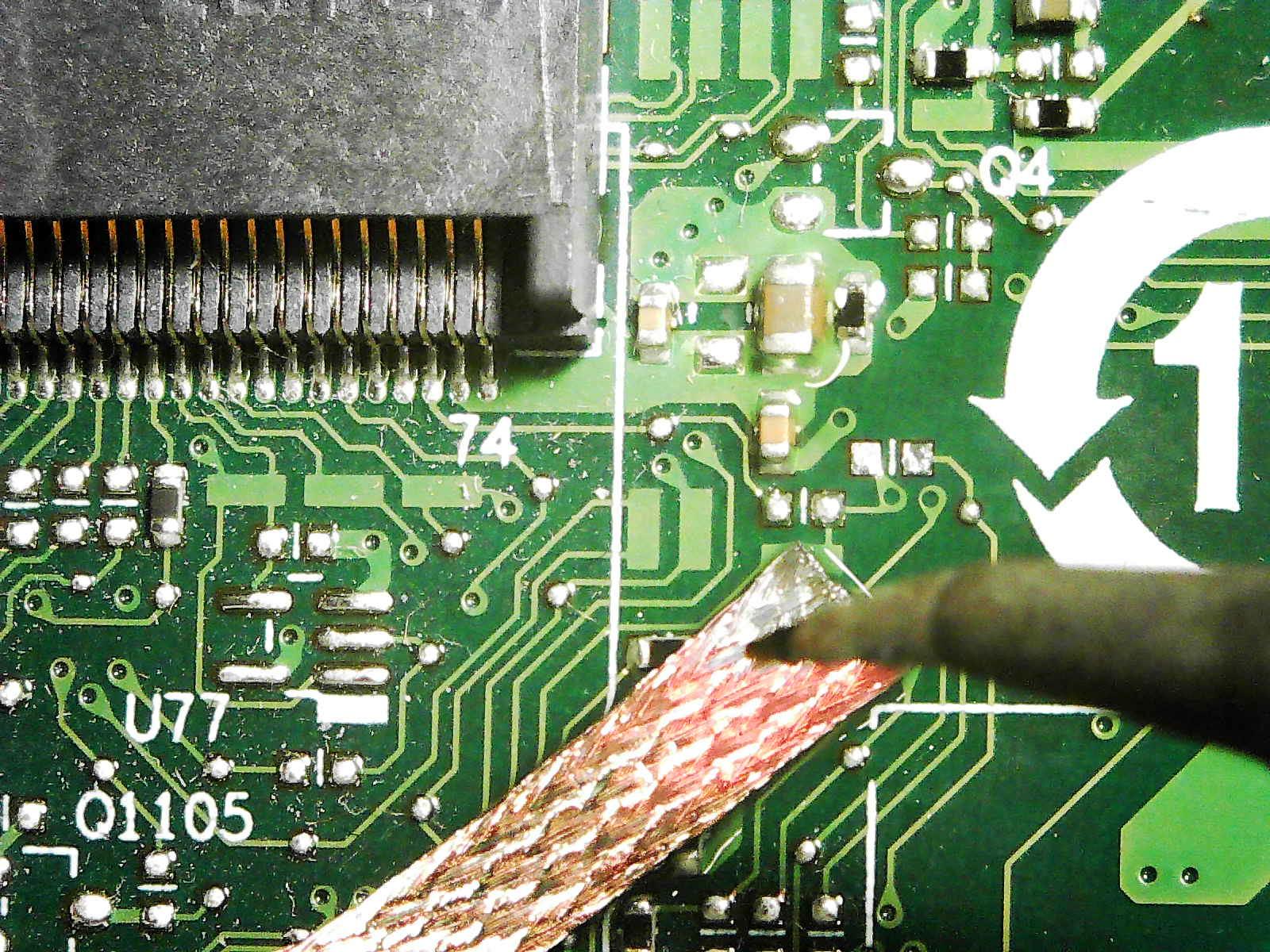
If you accidentally bridge a connection, or apply too much solder, solder wick will help in sucking the excess solder and unbridge the connections.
All set now!
Near the middle of the board, between the PCH chip and the 10 label, there is one resister that we have to move from one position to another.
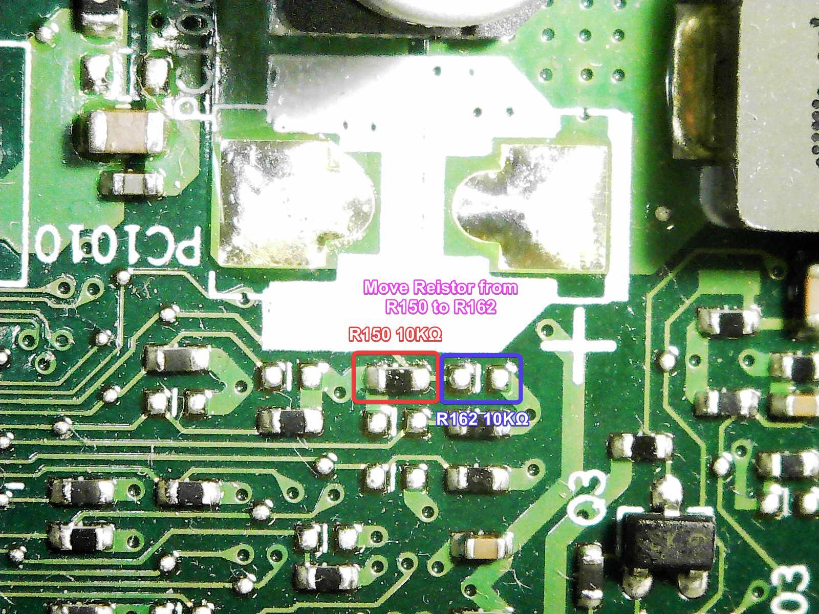
For M920Q Only - Move Resistor R150 to R162
For M920Q Only
For the M920Q models, desolder and move the Resistor R150 to R162. This will tell the motherboard to oeprate in M920X mode, allowing the second NVMe slot to be recognize in the BIOS.
For M720Q Only - Move Resistor R151 to R157
For the M720Q models, Resistor R150 does not exist. Instead, desolder and move the Resistor R151 to R157. This will tell the motherboard to oeprate in M920X mode, allowing the second M.2 slot to be recognize in the BIOS as a SATA only slot.
Moving the resistor can be a bit tricky,
Thankfully,this is a 10k ohm resistor, which you will have spares of if you have order extra components from Mouser.
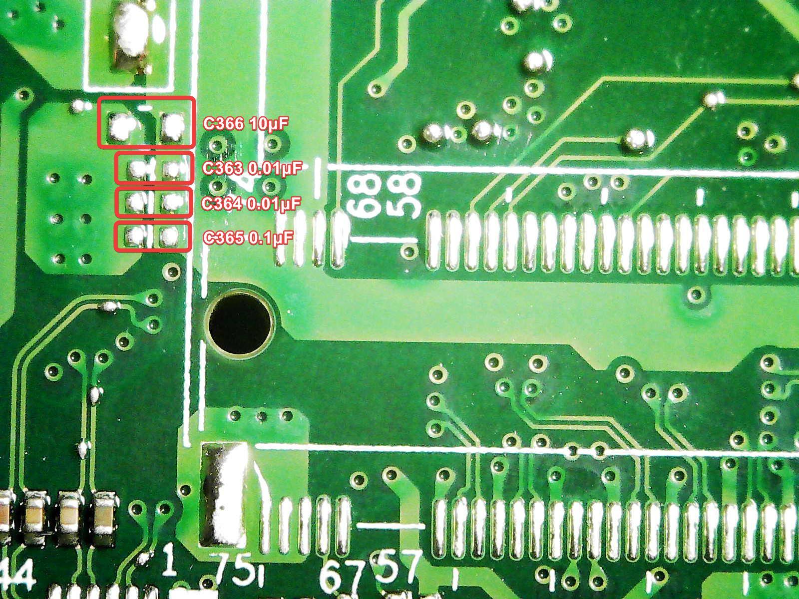
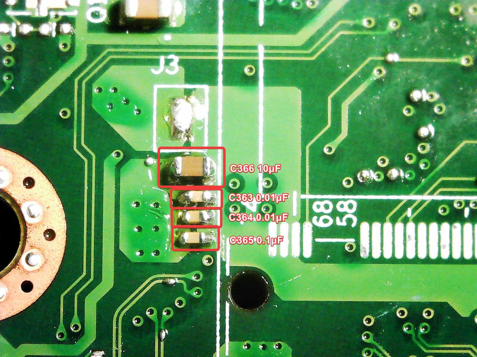
On the backside, there are 4 capacitors to solder on.
All set.
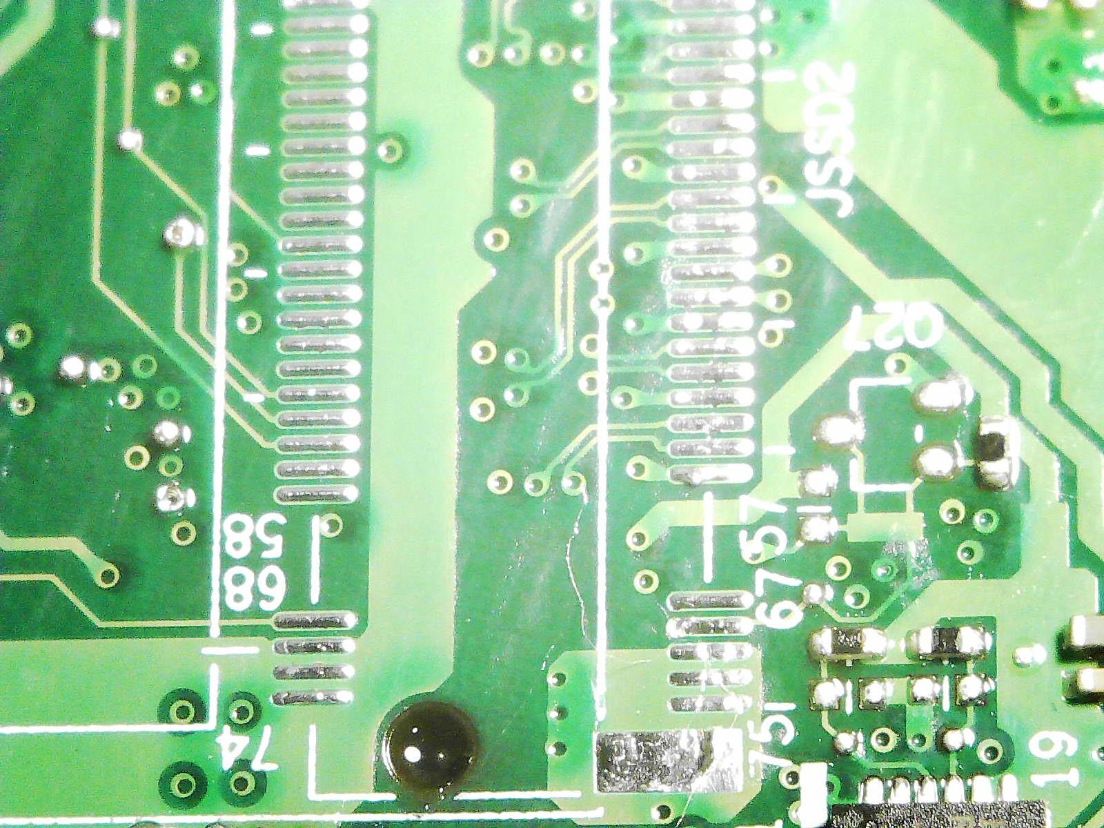
Now here comes the hard part, the M.2 slot soldering. First, use the solder wick to remove any of the original, factory solder. Use plenty of flux for this.
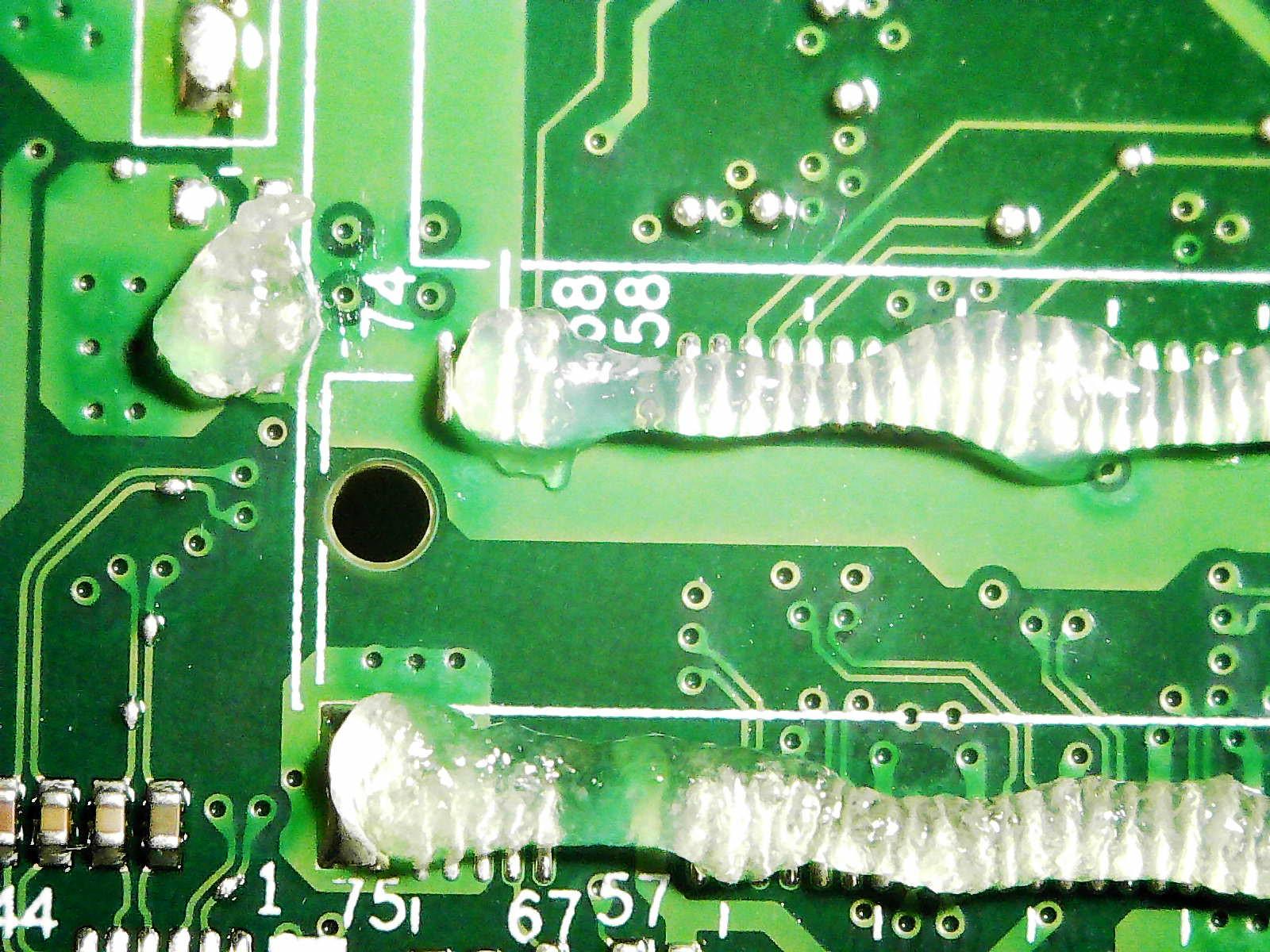
Shiny.
Tin the pads a little with leaded solder so its easier to melt.
The M.2 Slot sits nicely in place and the pads lines up.
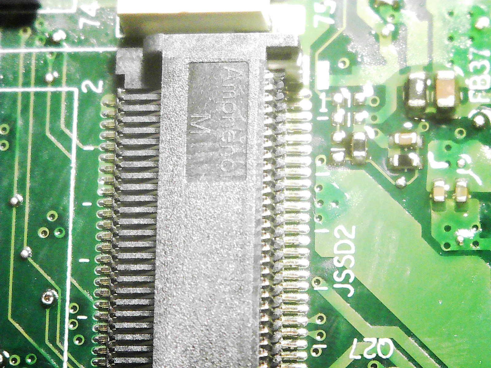
Apply flux,